A Beginner’s Guide to MIG Welding
Table of Contents:→ Types of Shielding Gas for MIG Welding → Components of a MIG Welding Setup → Push Welding vs. Pull Welding → What Is MIG Welding Used For? |
Metal inert gas welding, commonly referred to as MIG welding, is where many welders get their start. In this guide, we will review what a beginner needs to know, including the basic principles, common misconceptions, and what you need to get started with a MIG welding setup.
What Is MIG Welding?
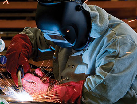
To start, let's define MIG welding. MIG welding, also known as gas metal arc welding (GMAW), is a welding process that utilizes a wire electrode to heat and join two metal pieces together. In MIG welding, an electric arc is created between the workpiece and the wire electrode, which melts the wire and fuses it with the base metal, creating a welded joint. The wire electrode is continually fed through the welding gun, which releases an inert gas (such as argon or helium) to shield the weld metal from oxidation and contamination.
MIG welding is widely considered a more beginner-friendly welding process. Here are a few reasons why:
- It is a semiautomatic process – the filler wire is automatically fed into the welding torch. This lets the operator focus on positioning the torch without worrying about manually feeding the wire.
- MIG welding equipment is comparatively easy to set up and use.
- MIG welding can be performed at high travel speeds, which makes it an efficient process for large welding projects.
Overall, MIG welding is a relatively easy welding process that can produce high-quality welds with minimal training and experience.
What Is Wire Feed Welding?
MIG welding uses a welding wire wound onto a spool or coil, or into a bulk package. To use the wire, MIG welding equipment packages include a wire feeder. A wire feeder consists of a set of drive rolls that pull the wire from its stored form and push it into and through a MIG gun to the weld. Many wire feeders also include an arm that holds a spool or coil of wire. Since the wire feeder is an integral part of a MIG welding setup, and many hose or cable connections are made on the wire feeder, some people colloquially refer to MIG welding as wire feed welding—a reference to the wire feeder.
Welding Wire Basics
There are four key factors to consider when welding with a MIG welder: wire composition, wire diameter, wire feed rate, and wire stick out. Selecting and using the correct values for these factors can help users create high-quality welds.
Wire Composition
Using the right welding wire for your MIG welding project or job is critical to successful welds. If the wire is not compatible with the material being welded, you may experience poor bonding, excessive spatter, and stubbing. Even if the incorrect wire seems to weld fine, welds made with the wrong wire may fail to provide the chemistry and mechanical performance you expect from the welded piece.
Your Linde representative can help you determine the right welding wire for your welding project. Your local Linde store stocks a wide range of available welding wires.
Wire Diameter
Wire diameter also plays an important role in your welding results. The chosen wire diameter helps determine the achievable amperage/heat and penetration levels and how fast your welding or travel speed can be. With too small a wire, you may not get the penetration you want and welding will take much longer than expected. On the other hand, if the wire diameter is too large, the amperage/heat required to melt it may cause damage like warping or distortion to the piece being welded, or holes from burn-through. Fortunately, many MIG welding machines come with charts—located either on the machine or in the manual— specifying which wire diameters should be used for different material thicknesses.
Wire Feed Speed Rate
Determining the appropriate wire feed speeds can be tricky, as the ideal setting will depend on other factors like travel speed, material thickness, transfer mode, and amperage. When not managed properly, the wire feed rate can contribute to defects like burn-through. Anywhere from 100 inches per minute to 500 inches per minute can be suitable for a wide range of MIG welding projects, with some wire feeders capable of speeds up to 800 inches per minute. The chart included with your machine will likely show different wire diameters, along with recommended wire feed speed rate and machine amperage settings to help you create effective welds.
Wire Stick Out
Another piece of the welding wire puzzle is called stick out. Stick out refers to the distance between the edge of the MIG gun nozzle to the point where the welding wire melts off—the amount that the wire “sticks out” from the gun. The ideal stick-out range is generally around 3/8 of an inch, a distance that should be maintained as you weld. Managing the wire stick out with consistent nozzle distance and angle takes time and practice to master but is important to success in MIG welding.
Types of Shielding Gas for MIG Welding
Argon/carbon dioxide mixtures are used as shielding gas for much of the MIG welding performed today. However, different welding procedures and requirements can call for pure argon or pure carbon dioxide as a shielding gas, or for two-component or even three-component gas blends, depending on the metal being welded and the individual job or project requirements.
For a more detailed guide to the types of shielding gas for MIG welding recommended by Linde Direct, visit our MIG Welding Gases Guide.
MIG Welding Transfer Modes
What does transfer mode mean? When the welding wire is melted, there are different ways that molten material can be transferred from the wire and MIG gun and deposited into the weld puddle. These various methods are known as transfer modes. The type of transfer mode used can affect max travel speeds, weld penetration, and weld appearance.
Short Circuit
In the short-circuit transfer mode, the tip of the welding wire makes contact with the weld puddle. In doing so, it creates a short circuit, hence the name. To overcome the short, the amperage increases, causing the wire to melt and be deposited. The wire continues to feed, restarting the arc, resulting in up to 200 short circuits per second and wire being deposited with each transfer of the wire material. This transfer mode results in average penetration, making it suitable for many different thicknesses and material types.
Globular
Globular transfer is generally used only on carbon steel, with pure CO2 shielding gas. In globular transfer, the wire touches the workpiece once to initiate the arc. Then, due to the higher heat of the arc, molten droplets or “globs” of material are ejected from the tip of the welding wire into the weld puddle. The globular transfer mode presents limitations, including welding orientation and creating excess spatter. Because of the higher heat input compared to short-circuit welding, this transfer mode is not effective for out-of-position welds and is used only with flat or horizontal welding joints. It can also require quite a bit of cleanup due to the amount of spatter it generates. This method is better suited for thicker materials, as welding thin materials with this transfer mode runs the risk of burn-through.
Spray Transfer
The spray transfer mode allows users to ramp things up with an even higher heat input, higher wire feed rates, and faster travel speeds than other transfer modes. Unlike globular transfer, in which large droplets or globs of material are ejected into the weld puddle, spray transfer ejects much smaller, uniform droplets one after the other, hundreds of times per minute. Due to the higher heat input and faster wire feed rate, spray transfer results in deep weld penetration. Therefore, it can be a suitable choice for thick materials, delivering high-quality, finished-looking welds with significantly less spatter than other modes.
Pulsed Spray Transfer
Pulsed spray transfer is similar to spray transfer, except the power source quickly modulates or “pulses” between a high-peak current, in which the material is transferred to the weld puddle, and a low-background current, which keeps the arc active but does not transfer any molten metal into the puddle. This significantly reduces heat input compared to spray transfer, allowing welders to achieve the weld quality of the spray transfer mode while maintaining a lower heat input. This makes it ideal for welding thinner materials.
Components of a MIG Welding Setup
These are the key components of a MIG welding setup:
MIG Welder
The MIG welder acts as a power source. From the welding machine, the operator can control parameters like voltage, amperage, and wire feed rate. Many MIG welding machines come equipped with a reference table for recommended voltage and wire feed settings based on parameters like the base material and material thickness.
Today, there is a wide range of different MIG welding power sources available. Many of the lower amperage models have the wire feeder built in, creating an all-in-one solution.
Ground Clamp and Cable
The ground clamp is meant to be attached to the workpiece or a metal workbench with a cable. The ground clamp closes the circuit between the workpiece and the welder so that an arc can be struck by the wire electrode coming out of the welding torch.
MIG Gun Assembly
The MIG gun feeds the wire electrode, which serves as a filler material. A trigger mechanism on the torch is used to start and stop the circuit that creates the welding arc while simultaneously controlling wire feed. The MIG gun also carries the shielding gas and dispenses it around the wire and the weld puddle to help stabilize the welding arc and prevent external contamination.
Wire Feeder
The wire feed mechanism pulls the welding wire from its spool and pushes it through the MIG gun on to the weld puddle. Adjustments can be made to both the wire feed speed and the tension of the wire to ensure smooth, consistent feeding.
Welding Gas Supply
An inert gas supply is required to shield the molten weld puddle from external contaminants, which can lead to defects and poor weld integrity. The gas flow rate is determined by a regulator/flowmeter connected to the gas cylinder. The gas flow should be sufficient to cover the weld pool, but not so intense that it causes the molten material to spatter. A good place to start is typically between 20 and 25 cubic feet per hour.
Push Welding vs. Pull Welding
MIG welding can be effective using either a pull method or a push method. Each method has distinct advantages and features to consider, and you may end up having a personal preference for one over the other after some experimenting and practice.
The Pull Method
A pull method is when the gun and arc are pulled in the direction of the weld (backhand) and the arc and electrode trail the weld path. Since the electrode is pointed back into the weld puddle in this case, this method generally creates deeper penetration and a narrower weld bead.
The Push Method
A push method is when the gun and arc are pushed in the direction of the weld (forehand) and the arc and electrode lead the weld path. Since the electrode is pointed away from the weld puddle and pushing it along, this technique usually results in a shallow, wider joint than with a pull method. The push technique also generally provides greater visibility, as the torch is pointed toward the remaining weld path with no visual obstructions.
What Is MIG Welding Used For?
MIG welding can be used to weld a wide variety of materials, including both ferrous and nonferrous alloys. Due to its reputation as a beginner-friendly welding method, it is commonly used by new welders for DIY projects. However, MIG isn’t just for beginners. It is also used by professional welders with years or even decades of experience for jobs of all kinds. MIG welding can be seen in many types of manufacturing and production processes in numerous industries, from agriculture to oil and gas.
Are MIG Welding and GMAW the Same Thing?
GMAW stands for gas metal arc welding, an overarching term that covers both MIG and MAG processes. These processes use a gas, metal (in the form of a welding wire), and an electric arc. The difference between MIG and MAG welding is the type of gas used: MIG welding uses an inert gas while MAG welding uses an active gas. Other welding types include TIG, stick, oxy-fuel, and submerged arc which are all classified differently.
For a more in-depth look at MIG welding and GMAW, check out this blog post.
GMAW vs. FCAW
You may have seen the terms GMAW and FCAW discussed in other welding resources, and the similarity in the acronyms can make it tricky to differentiate between the two. GMAW stands for gas metal arc welding and FCAW stands for flux-core arc welding.
How Does Flux-Core Welding Work?
Flux-core welding has many similarities with MIG welding. They both use MIG welding equipment, wire that is packaged on a spool or coil, and, in many cases, a shielding gas. The key difference is that rather than the solid wire electrode used in MIG welding, FCAW welding uses a tubular wire filled with alloying ingredients and flux. Some flux-cored wires are manufactured to be used with a shielding gas, as with MIG welding, but with additional chemical and mechanical properties incorporated by the ingredients within the tubular wire core itself.
Other types of FCAW wire are specifically designed to function without the need for a shielding gas. Instead, the flux inside the wire provides a gas shield for the weld as it is melted.
Your local Linde team is experienced with GMAW and FCAW processes. You can rely on them for information on building a MIG welding setup, choosing an appropriate wire and shielding gas, and for help troubleshooting your welding process.
Contact your local Linde representative today.
NOTE
The information provided here is just an overview offered for the convenience of the reader and not a substitute for education, training, and development of the skills needed to use a cutting torch safely and effectively.

